

















 English
 Français
 Deutsch
 Português
 Español
 русский
  한국어
한국어 العربية
 Italiano
 Indonesia
 Schweiz
 Polski
 Nederlands
 ישראל - עברית
 Perzisch
 ไทย
ไทย 日本語
日本語 ኢትዮ-አማርኛ
 Việt Nam
 Kiswahili
 Srpski
 Ελληνικά
 繁體中文
繁體中文How Cooling Fans Help Prevent Evaporator Coil Frost
09/11/2026Why Evaporator Coils Freeze
Frost forms when a coil surface falls below the freezing point and moisture in the air condenses and freezes on that surface. In a precision air conditioner, low airflow is a common contributor because less warm air passes across the coil while refrigeration capacity remains available. The coil becomes colder, and the first layer of ice further restricts airflow.
This creates a self-reinforcing problem. As ice builds, pressure drop increases and air volume falls. Cooling performance declines, sensors may read misleading conditions, and liquid refrigerant may return toward the compressor in some systems. Early detection is safer than waiting for a fully blocked coil.
The Airflow-Coil Temperature Relationship
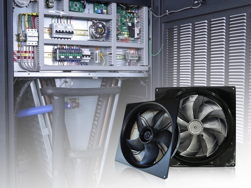
The fan controls how much sensible and latent heat reaches the evaporator. When airflow is within the intended range, heat is distributed across the coil and refrigerant can evaporate as designed. When airflow is too low or highly uneven, some circuits or coil areas may operate at a much lower surface temperature than others.
A speed percentage alone does not prove that airflow is adequate. Filter loading, coil contamination, closed dampers, blocked grilles, belt slip, and incorrect rotation can all reduce delivered air even when the motor is running.
Common Air-Side Causes
Dirty filters are one of the most frequent restrictions. A filter that appears only moderately loaded can still create enough pressure loss to move the fan away from its normal operating point. Dust on the coil adds resistance and insulates heat-transfer surfaces. Furniture, stored materials, closed floor tiles, or collapsed flexible ducts can block the external path.
Uneven inlet conditions are another cause. If a cabinet panel, cable bundle, or poorly fitted filter directs air toward only part of the coil, the low-flow section may frost while the unit's average airflow seems acceptable.
Fan and Compressor Coordination
The control sequence should establish airflow before enabling mechanical cooling. A fan proof signal based only on a run command is weak protection; speed feedback, differential pressure, or an airflow switch gives better evidence. If airflow falls below a safe threshold, the controller should unload or stop the compressor and generate a clear alarm.
At low cooling loads, fan speed and refrigeration capacity must be reduced in a coordinated manner. Allowing the compressor to maintain aggressive suction conditions while the fan operates at minimum speed can push the coil toward freezing.
Detection and Recovery
Useful warning indicators include rising filter differential pressure, falling suction temperature, abnormal superheat, low air differential pressure, increasing fan speed at constant demand, and a widening temperature difference across the coil. Multiple signals reduce false alarms and identify problems before visible ice develops.
If frost is detected, refrigeration should be stopped according to the unit's approved sequence while the fan may continue moving warmer air across the coil. Do not chip ice from the fins. After thawing, inspect filters, drainage, coil cleanliness, sensors, fan rotation, and control settings before restarting.
Designing Out the Risk
Select the fan for both clean and loaded-filter conditions, distribute air evenly across the coil, and provide accessible pressure measurement points. Set a realistic minimum airflow and verify it during commissioning. Maintenance alarms should respond to actual pressure or performance rather than calendar time alone.
Coil frost prevention is a system function. A reliable fan, clean air path, valid airflow proof, and coordinated refrigeration controls work together to keep the evaporator within a safe operating range.
Conclusion
Preventing coil frost requires verified airflow before and during refrigeration operation. Clean components, minimum-flow protection, and coordinated controls stop a small restriction from becoming a complete loss of cooling.