

















 English
 Français
 Deutsch
 Português
 Español
 русский
  한국어
한국어 العربية
 Italiano
 Indonesia
 Schweiz
 Polski
 Nederlands
 ישראל - עברית
 Perzisch
 ไทย
ไทย 日本語
日本語 ኢትዮ-አማርኛ
 Việt Nam
 Kiswahili
 Srpski
 Ελληνικά
 繁體中文
繁體中文Integrating GTW091PBU29E-V007 Controls and Monitoring into Data Center Cooling Systems
09/20/2026From Fixed Airflow to Demand-Based Cooling
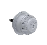
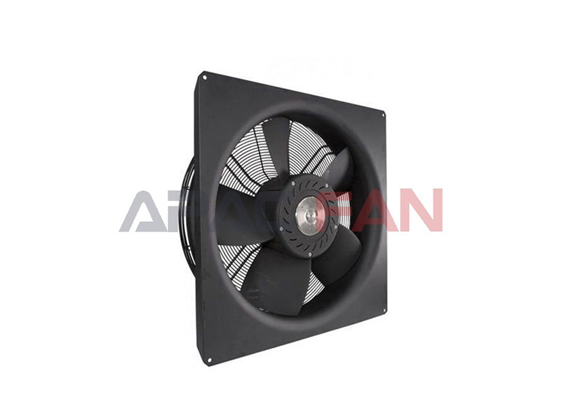
Data center thermal loads change with IT utilization, equipment distribution, outdoor conditions, and the operating state of the cooling plant. A fan that can respond to a control signal gives the equipment designer a way to match airflow to current demand. The Delta GTW091PBU29E-V007 combines an EC motor with 0-10 VDC and PWM inputs and an RS485 interface. This allows the fan to participate in a controlled cooling assembly instead of functioning only as an across-the-line, fixed-speed device.
The control strategy should be defined at system level. Possible control variables include supply-air temperature, return-air temperature, differential pressure, cooling-coil demand, or a supervisory command from the cooling unit. The fan itself provides the actuation capability, but stable temperature and pressure control depend on appropriate sensors, setpoints, limits, and sequencing. Minimum airflow, condensation avoidance, freeze protection, and redundancy responses should all be considered before the controller is commissioned.
Using 0-10 VDC and PWM Inputs
The specification describes several ways to command speed. Full speed can be requested by shorting the 0-10 V input to the fan’s +10 V output. A 1-10 kΩ variable resistor may be connected between +10 V, ground, and the 0-10 V terminal for manual adjustment. An external 0-10 VDC source can also provide the command, with its positive lead connected to the 0-10 V terminal and its negative lead connected to ground. These methods are useful for commissioning, local control, or connection to a building or equipment controller.
PWM control is supported with a 10 VDC amplitude within ±5% and a frequency range from 100 Hz to 100 kHz. The published control curve indicates a commanded range beginning around 0.5 V or 5% PWM and reaching the active speed region from approximately 1.5 V or 15% PWM upward. Maximum-speed tolerance is listed as ±5%. The specification also notes that speed can fall below the expected lower bound if the supply voltage is outside the rated range, the fan reaches its power limit, or ambient temperature exceeds the specified limit. Control commissioning should therefore compare command, actual speed, power, and operating conditions rather than assuming that signal percentage always equals airflow percentage.
RS485 Communication and Status Visibility
The fan includes an RS485 control bus using Modbus V1.3 RTU at 9600 baud with 8N1 framing. The documented functions include control-mode selection, speed and power-consumption monitoring, multiple-fan control, and status polling. Delta specifies a polling interval greater than 100 milliseconds and an idle-mode differential voltage above 0.3 V between RS485 A and B. A shielded Modbus serial cable is required for better communication quality, with the shield connected to protective ground at one end of each cable.
For data center cooling equipment, communications can support operating visibility and fault diagnosis. A supervisory controller may compare command and reported speed, observe power demand, and patrol multiple fans. Communication design must still address network topology, addressing, termination, grounding, cable routing, and failure behavior. The cooling unit should define what happens if communications are lost: for example, whether the fan holds a previous command, follows a hardwired signal, or moves to a safe fallback determined by the system designer.
Protection and Start-Up Behavior
The GTW091PBU29E-V007 includes locked-rotor protection, abnormal-voltage protection, and over-temperature protection. It can initiate start-up while reverse rotation is below 500 RPM, and it uses a soft-start sequence from 0 to 100% speed over approximately 30 seconds. These functions are relevant in multi-fan cooling systems where pressure transients, backflow, or adjacent operating fans may cause a stopped impeller to rotate.
An alarm relay and voltage/current monitoring outputs are listed in the specification. The normally closed relay contact is rated at 2 A and 250 VAC; the NC-to-COM circuit is closed in the normal state and open in the abnormal state. The equipment controller should interpret this contact together with speed and electrical data. A fault strategy may include alarming, increasing the output of remaining fans, reducing thermal load, or starting redundant cooling equipment. The precise sequence depends on the data center’s resilience design and should be validated during integrated testing.
Installation Details That Protect Reliability
The fan is rated IP55 only when the installation preserves the intended enclosure and sealing conditions. Delta provides specific cable-gland and motor-cover instructions. Cable diameters must match the selected gland, only one cable should pass through each gland, unused glands should retain their dummy seals, and cables should leave the gland facing downward to reduce the risk of water following the cable into the motor enclosure. The wiring cover screws are tightened diagonally in two stages, with 10 kgf·cm in the first round and 17 kgf·cm in the second round, each with ±10% tolerance.
Mechanical handling also matters. At 60 kg, the fan requires appropriate lifting and support; the blades must not be used as lifting points. The finished structure must have sufficient integrity, anti-loosening fasteners are recommended, and the fan should remain at least 25 mm from surrounding components. Where a nozzle is installed, alignment and relative position should be checked. Incorrect mounting can introduce vibration, restrict airflow, compromise waterproofing, or make service access unsafe.
Maintenance Planning for Continuous Cooling
Delta recommends regular maintenance inspections at six-month intervals. Items include abnormal noise or vibration, ambient temperature and humidity, input and control voltage, foreign objects, oil or water, burning odors, blocked inlet or discharge paths, loose fasteners or cables, damage or aging, and dust accumulation on the fan body. These checks fit naturally into a data center cooling maintenance program because airflow degradation can develop gradually as filters load, debris accumulates, or connections loosen.
Before maintenance, power must be isolated and personnel should wait five minutes for discharge. A grounding check is mandatory before use, and the wiring cover must be correctly installed before energizing the fan. The specification states an L10 life of 60,000 hours at 40 °C and 15 to 65% relative humidity. L10 is a statistical bearing-life measure under stated conditions, not a guarantee that every fan will operate for the same duration. Trending speed, power, alarms, noise, and vibration can help operators identify changes before they affect cooling capacity.
Integration Summary
For a data center application, GTW091PBU29E-V007 should be integrated as part of a complete control and airflow design. Confirm the electrical supply, select either 0-10 VDC or PWM as the primary speed command, engineer the RS485 network, map alarm behavior, and establish a safe fallback mode. Preserve IP55 installation details, provide adequate structural support, and commission the fan across expected operating states rather than at a single full-speed point.
With its high-airflow EC platform, configurable speed input, Modbus visibility, alarm relay, and documented protection functions, the GTW091PBU29E-V007 can support controlled data center cooling equipment. Reliable results depend on disciplined integration: verified wiring, stable control logic, correct mechanical installation, and recurring inspection.