

















 English
 Français
 Deutsch
 Português
 Español
 русский
  한국어
한국어 العربية
 Italiano
 Indonesia
 Schweiz
 Polski
 Nederlands
 ישראל - עברית
 Perzisch
 ไทย
ไทย 日本語
日本語 ኢትዮ-አማርኛ
 Việt Nam
 Kiswahili
 Srpski
 Ελληνικά
 繁體中文
繁體中文Centrifugal Fans in AHUs: Types, Features and Applications
08/13/2026The Role of a Centrifugal Fan
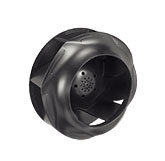
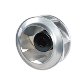
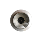
A centrifugal fan draws air into the center of a rotating wheel and redirects it outward through centrifugal action. This change in direction allows the fan to develop the pressure needed to move air through filters, coils, dampers, heat exchangers, silencers, and duct networks. In an AHU, the fan is selected as part of a system rather than as an isolated airflow source. Its geometry influences efficiency, sound, footprint, contamination tolerance, and control range. Understanding the main wheel and housing options helps designers choose equipment that fits the pressure duty, air quality, maintenance plan, and spatial constraints of the installation.
Forward-Curved Fans
Forward-curved wheels use many shallow blades that curve in the direction of rotation. They can provide useful airflow from a relatively compact wheel and have historically been common in smaller comfort-air units. Their power characteristic and efficiency range require careful selection, particularly when system resistance is uncertain. They are generally better suited to clean air because dust can accumulate on closely spaced blades and disturb balance. Speed control can extend their usefulness, but an operating point should not be chosen solely because it meets one airflow-and-pressure coordinate. Engineers also need to examine motor loading, sound, cabinet effects, and behavior across expected filter and damper conditions.
Backward-Curved and Backward-Inclined Fans
Backward-curved and backward-inclined blades sweep opposite the direction of rotation at their outer edge. These wheels are widely used where energy performance and stable operation over a practical range are priorities. Their power demand often behaves favorably compared with some alternatives, although the final motor selection must still cover the actual system curve and control sequence. Airfoil-bladed versions can achieve strong aerodynamic performance in clean-air service, while simpler plate blades may tolerate contamination or cleaning requirements differently. The distinction between blade profiles matters: two fans described broadly as backward-curved can have different efficiency, sound, strength, and fouling characteristics.
Housed Fans and Scroll Casings
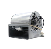
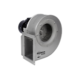
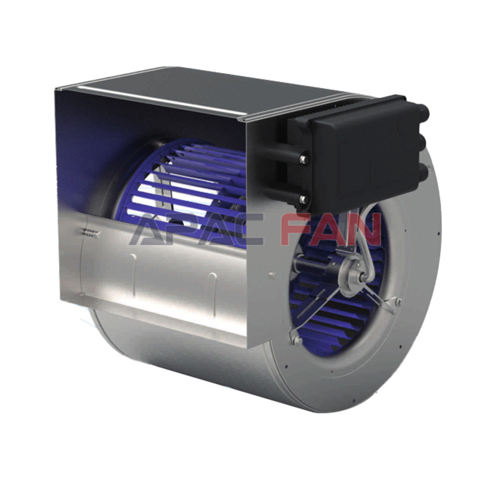
A housed centrifugal fan surrounds the wheel with a scroll-shaped casing that collects the discharge air and converts part of its velocity into static pressure. The casing provides a defined outlet that can connect to ductwork, but it also dictates orientation and consumes space. In a traditional draw-through or blow-through AHU, housed fans may be belt driven or directly coupled. The inlet condition is critical; elbows, guards, structural members, or poorly placed dampers can create nonuniform flow into the wheel. Outlet transitions also need enough length and appropriate geometry. Catalog performance is based on defined test arrangements, so a cramped field connection can create system effects that reduce delivered airflow.
Plenum and Plug Fans
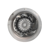
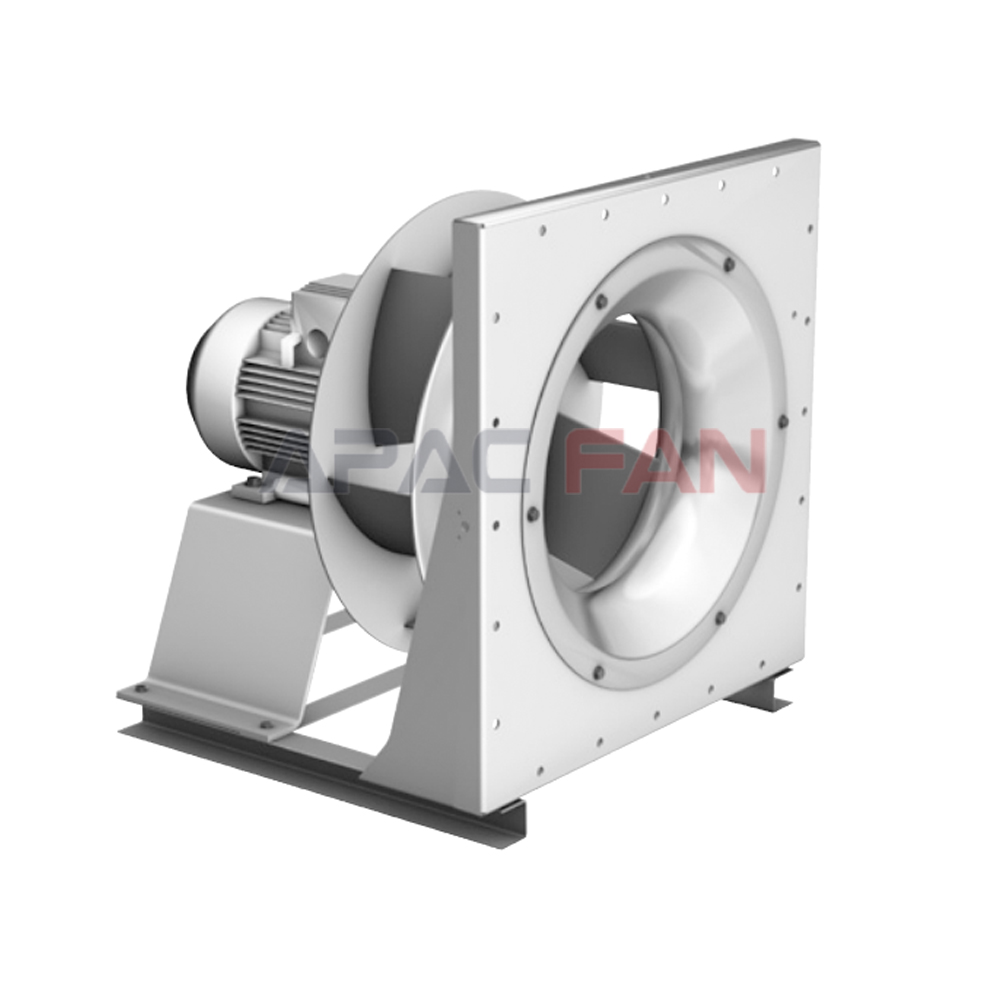
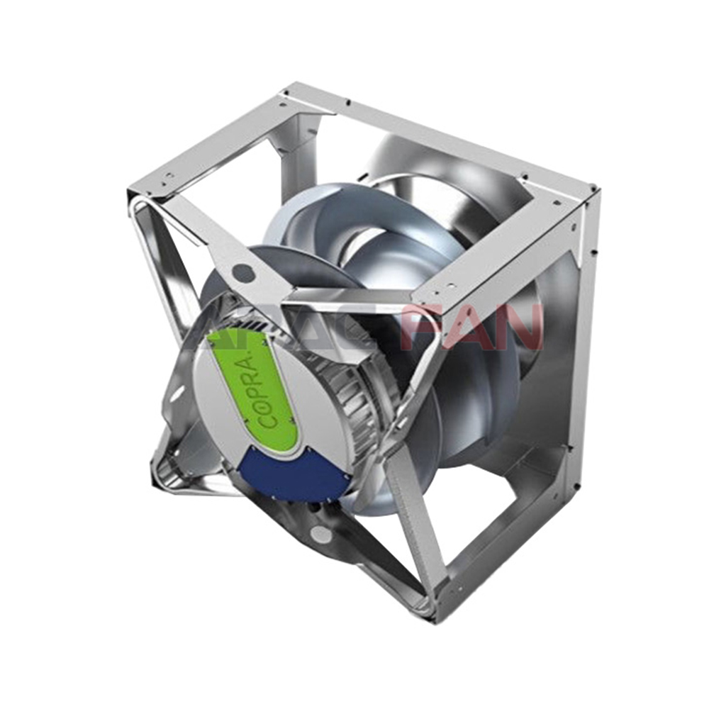
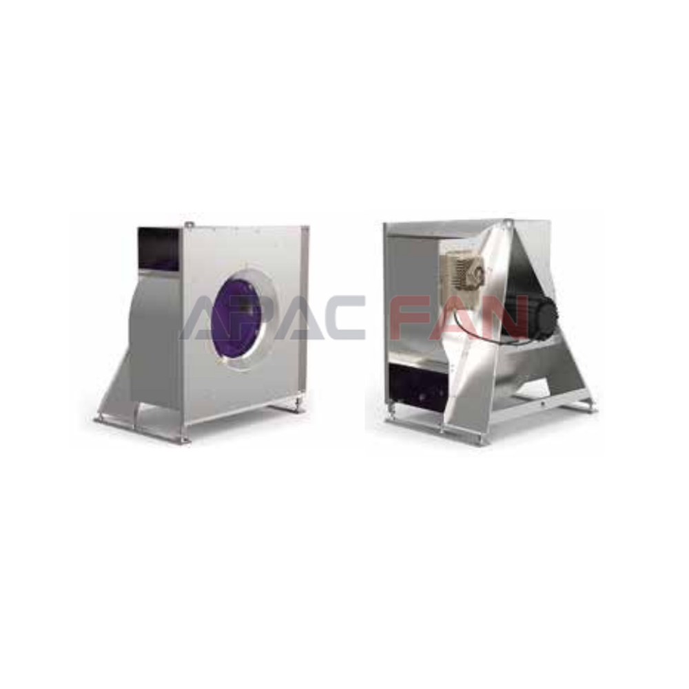
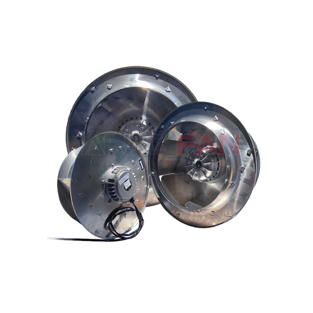
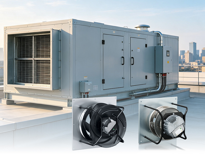
Plenum fans, often called plug fans in AHU practice, use a centrifugal wheel without a scroll housing. The AHU casing or fan plenum receives the air discharged in all directions, and static pressure is recovered within that space. This arrangement offers flexible discharge locations and can reduce the space required for a conventional scroll. It also suits direct-drive motors and multi-fan arrays. However, the surrounding plenum becomes part of the aerodynamic design. Clearances, nearby coils, access doors, structural rails, and discharge openings affect performance. The absence of a scroll does not eliminate system effect; it moves the pressure-recovery task into the unit casing.
Drive Arrangements
Belt-driven fans allow motor speed and wheel speed to differ through pulley selection. They can be practical where traditional service skills and component availability are important, but belts require tensioning, alignment, guarding, and periodic replacement. Belt dust and drive losses may be undesirable in clean applications. Direct-drive arrangements remove belts and place the wheel on the motor shaft or connect it through a direct coupling. They reduce routine drive maintenance and pair naturally with speed-controlled motors. The choice affects fan length, bearing arrangement, service access, vibration behavior, and replacement procedures. It should be made in the context of the whole AHU rather than treated as a simple efficiency preference.
Pressure, Efficiency, and Operating Range
Fan curves describe the relationship among airflow, pressure, speed, and power for a tested configuration. The installed operating point occurs where the fan curve intersects the system curve. Filters loading with dust, dampers moving, and terminal boxes changing position cause that point to shift. A sound selection maintains useful efficiency and stable flow across these conditions. Operating too close to stall can create pulsation, noise, and unreliable control. Oversizing is also harmful because it may force prolonged low-speed operation or waste pressure across dampers. Selection software is valuable, but designers should understand the assumptions behind density, inlet conditions, drive losses, and pressure definitions.
Application by Air Quality and Duty
Comfort AHUs generally handle filtered air, allowing a broad choice of wheel designs. Industrial or process units may face grease, fibers, dust, corrosive vapors, high temperature, or frequent washdown. These conditions influence blade shape, materials, coatings, seals, bearings, motor location, and access for cleaning. A high-efficiency airfoil wheel intended for clean supply air may not remain efficient if deposits build on its surfaces. Exhaust and energy-recovery systems also require attention to contamination and leakage paths. The correct fan is therefore defined not only by airflow and pressure but by what the air contains and how the equipment will be maintained.
Noise and Vibration Control
Centrifugal fans generate aerodynamic sound at the inlet and discharge, while motors, bearings, belts, and structural components contribute mechanical noise. A good design starts by selecting a reasonable wheel speed and operating point. It then manages transmission through flexible connectors, isolation bases where appropriate, casing construction, duct lining or silencers, and well-designed transitions. Isolation cannot cure aerodynamic instability, and a silencer can add pressure loss that shifts the operating point. Vibration monitoring should distinguish normal rotational components from imbalance, misalignment, bearing deterioration, looseness, or resonance. Keeping the wheel clean and the drive aligned is often as important as the initial isolation specification.
Making a Practical Selection
Begin with credible airflow and pressure requirements, then evaluate the full operating envelope. Compare wheel types using efficiency, sound data, motor power, dimensions, access, contamination tolerance, and controllability. Check whether the AHU layout provides uniform inlet flow and adequate discharge recovery. Confirm that filters can be replaced, bearings can be reached, belts can be adjusted if used, and the wheel can be cleaned without dismantling unrelated sections. Finally, coordinate sensors and control sequences with the selected fan. Centrifugal fans remain central to AHU design because their many configurations can serve diverse duties, but that flexibility rewards careful system-level engineering.