

















 English
 Français
 Deutsch
 Português
 Español
 русский
  한국어
한국어 العربية
 Italiano
 Indonesia
 Schweiz
 Polski
 Nederlands
 ישראל - עברית
 Perzisch
 ไทย
ไทย 日本語
日本語 ኢትዮ-አማርኛ
 Việt Nam
 Kiswahili
 Srpski
 Ελληνικά
 繁體中文
繁體中文What Is an AHU Fan?
08/10/2026Start with the Air-Handling System
An air-handling unit is an assembly that may circulate, filter, heat, cool, recover energy, humidify, dehumidify, or mix air. The fan provides the pressure rise that moves air through these internal components and through connected ductwork. For the fan as the airflow-producing component within an air handling unit, the useful starting point is therefore the system duty, not an isolated product label. Designers should define the required air quantity, the intended operating schedule, the air path, and the pressure losses created by filters, coils, dampers, silencers, heat-recovery devices, terminals, and ducts. This system view prevents a common mistake: choosing a fan that looks suitable in a catalogue but cannot meet the installed duty efficiently or controllably.
Understand Airflow and Pressure
Airflow describes how much air the fan moves, while pressure expresses the resistance that the fan must overcome. These quantities are linked by the operating point, where the fan performance curve intersects the system resistance curve. Internal AHU losses and external duct losses both matter, and their values change with airflow and component condition. A clean filter does not impose the same resistance as a loaded filter, and an open damper does not behave like a throttled damper. Work on AHU fan fundamentals should document which condition each pressure value represents. Without that definition, comparisons between fans can be misleading even when every published number is technically correct.
Read Fan Curves in Context
A fan curve is not a guarantee that every point on the graph is equally desirable. The selected point should sit inside the manufacturer’s permitted operating region and should be reviewed together with efficiency, input power, speed, sound, motor loading, and control limits. Density and test configuration also deserve attention when project conditions differ from rating conditions. When evaluating the fan as the airflow-producing component within an air handling unit, use certified or manufacturer-issued performance data whenever available, and ask how the fan was tested. The installed AHU inlet and outlet geometry can alter flow quality, so laboratory performance should be combined with realistic allowances for the final arrangement rather than treated as an automatic field result.
Consider Fan and Motor Configuration
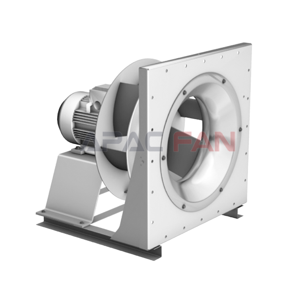
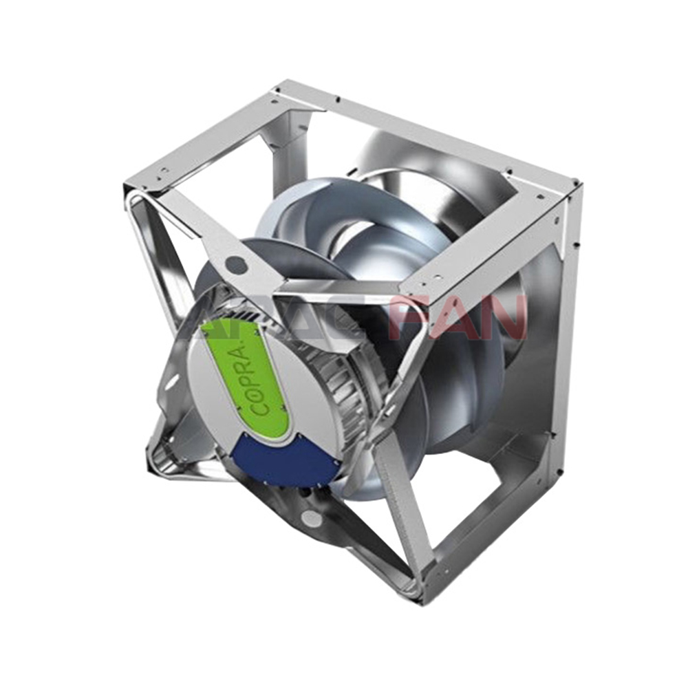
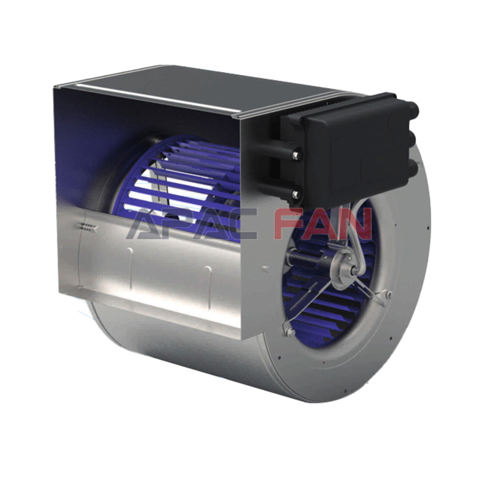
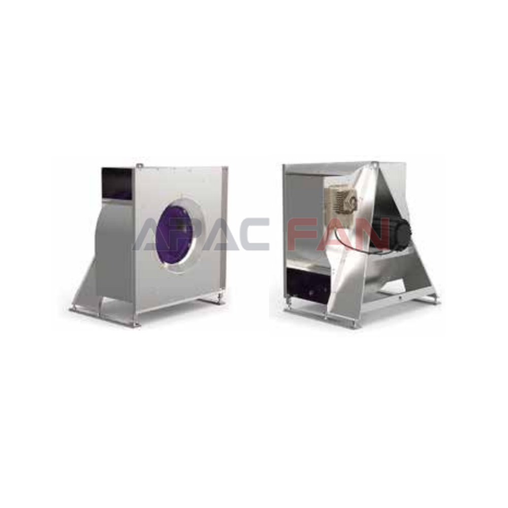
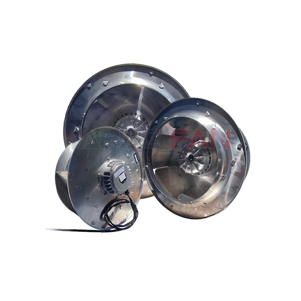
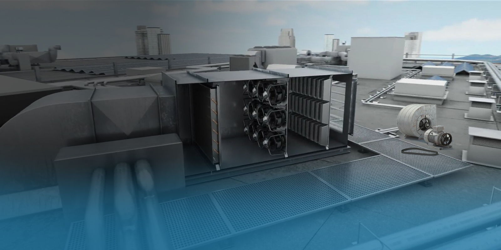
AHUs can use housed centrifugal fans, plug fans, fan arrays, and other arrangements selected for the required duty and unit architecture. Motors may be connected through belts, directly coupled, or integrated with the fan assembly. Each choice affects footprint, access, speed control, alignment, replacement work, and the way air leaves the fan section. The subject of AHU fan fundamentals is therefore broader than choosing an impeller. Engineers should consider the fan, motor, drive, power electronics, guards, supports, wiring, controls, and surrounding casing as one functional package. A compact arrangement is valuable only when it still provides safe access and acceptable airflow into and out of the fan.
Plan Controls and Part-Load Operation
Variable airflow is common because building and process demand rarely stays at one condition. Speed control can align fan output with demand, but the control sequence must be engineered rather than assumed. Sensors need suitable locations, setpoints must reflect the real service objective, and minimum speeds must respect motor cooling, control stability, ventilation requirements, and manufacturer limits. In the fan as the airflow-producing component within an air handling unit, part-load behavior may be as important as the design point. Review how the fan starts, stops, ramps, responds to alarms, and operates when filters load or zones close. Integrated controls should also be coordinated with the building management system so commands, feedback, status, and fault handling are unambiguous.
Account for Installation Effects
Poor inlet flow, abrupt transitions, close elbows, obstructions, leakage, and badly arranged discharge connections can create system effect. Turbulence or swirl near the fan can reduce delivered performance and may increase sound or vibration. Adequate straight approaches are helpful where space allows, but actual clearance requirements should come from the fan and AHU manufacturer. For AHU fan fundamentals, dimensional coordination should begin before equipment is ordered. Review service doors, coil pull space, filter access, cable routes, flexible connections, isolation, drainage, and lifting paths. A technically capable fan can still become a poor installation if surrounding details force nonuniform airflow or make routine service impractical.
Manage Noise and Vibration
Sound data should be interpreted by frequency band, operating condition, test method, and installation, not by a single headline number alone. Airborne noise can travel through ducts, casing panels, openings, and structure, while mechanical vibration can be transmitted through supports and connections. A good the fan as the airflow-producing component within an air handling unit strategy combines appropriate fan selection with stable operation, balanced rotating parts, sound casing design, suitable isolation, and sensible duct geometry. Simply adding a silencer can increase resistance and move the fan operating point. Acoustic treatment should therefore be included in pressure calculations and checked for regenerated noise, access, hygiene, and compatibility with the air stream.
Commission the Complete System
Commissioning connects design intent to actual operation. Before startup, verify rotation, cleanliness, fasteners, guards, electrical protection, sensor installation, damper position, and unobstructed airflow. During testing, record airflow, relevant pressures, speed, electrical input, vibration, sound observations, and control response using appropriate instruments and safe procedures. For AHU fan fundamentals, compare measured results with approved submittals and the documented system condition. If airflow is low, avoid increasing speed immediately. First examine filters, coils, dampers, duct leakage, blocked inlets, measurement locations, rotation, and system effect. Correcting the real cause is safer than using speed to mask excess resistance or a faulty reading.
Maintain Reliable Performance
Maintenance should be based on equipment instructions, operating environment, duty, and observed condition. Typical tasks include inspecting contamination, corrosion, fasteners, guards, wiring, sensors, drains, flexible connections, bearings where applicable, belts where fitted, and the fan wheel or impeller. Cleaning methods must suit the materials and must not disturb balance or damage electronics. In the fan as the airflow-producing component within an air handling unit, trend information is often more useful than one isolated reading: changes in vibration, sound, speed command, pressure, airflow, or power can reveal developing restrictions or mechanical problems. After work is completed, restore guards and access panels and confirm that the unit returns to its intended control mode.
Make a Defensible Engineering Decision
A sound engineering decision records assumptions and uncertainties. State the design and minimum airflow, pressure basis, air density, temperature range, filtration condition, redundancy needs, electrical supply, control interface, acoustic criteria, available space, access needs, and applicable project requirements. Then compare manufacturer selections on the same basis. For AHU fan fundamentals, avoid universal claims such as one motor technology always being best or one fan style always saving a fixed percentage. Results depend on duty, operating profile, system resistance, component sizing, control logic, installation, and maintenance. When information is incomplete, request verified data or leave the conclusion open rather than filling the gap with an attractive but unsupported figure.
Frequently Asked Questions
What information is required before choosing an AHU fan?
At minimum, define airflow, pressure basis, air conditions, filtration condition, operating profile, control needs, electrical supply, space, sound expectations, and applicable project requirements.
Can a fan be selected from airflow alone?
No. Airflow must be considered with system resistance, the fan curve, power, speed, sound, installation, controls, and the manufacturer’s permitted operating range.
Why can installed performance differ from catalogue performance?
Laboratory ratings use defined test arrangements. Inlet swirl, abrupt transitions, obstructions, leakage, component condition, density, and measurement practice can change field results.